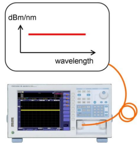
An Optical Spectrum Analyzer (or OSA) is a precision instrument designed to measure and display the distribution of power of an optical source over a specified wavelength span. An OSA trace displays power in the vertical scale and the wavelength in the horizontal scale.
The expanding field of optics related applications has created a vast variety of industries and organizations that require advanced optical spectral measurements for both R&D and manufacturing. These industries include telecommunications, consumer electronics, healthcare, life science/medical research, security, sensing, microscopy, and gas/chemical analysis, and environmental monitoring.
Yokogawa (formerly Ando) is the global leader in optical spectrum analyzers, delivering high quality, cutting edge technology with dependability, performance and flexibility for over thirty years.
Band | Optical communications | VIS | VIS & optical
communications | exNIR | MWIR | MWIR |
| Model Number | AQ6370D-12 | AQ6370D-22 | AQ6373B | AQ6374 | AQ6375B | AQ6376 | AQ6377 |
| |  |  | 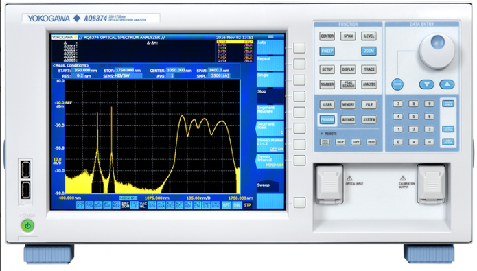 | 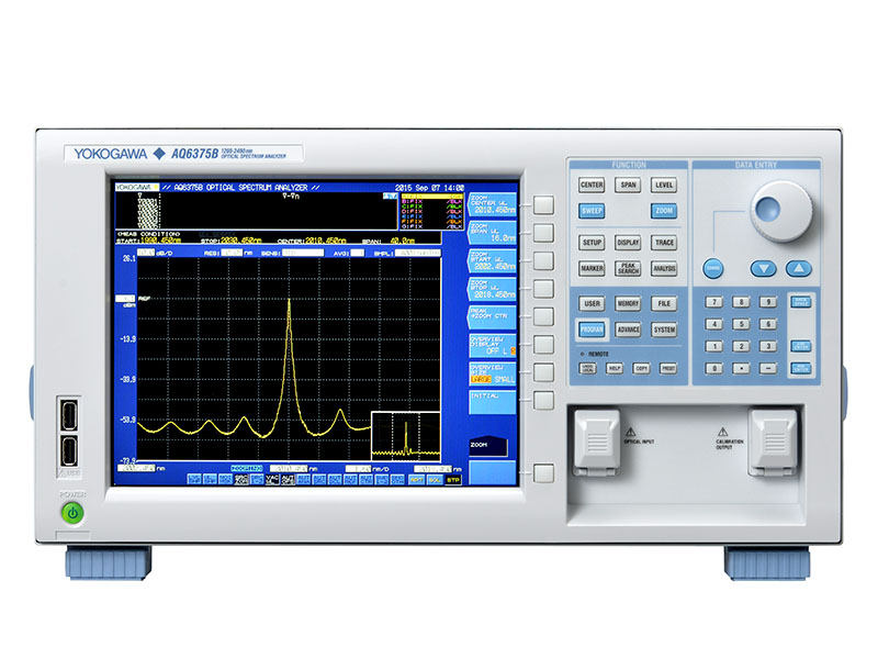 |  |  |
| Wavelength Range | 600 - 1700 nm | 350 - 1200 nm | 350 - 1750 nm | 1200 nm - 2400 nm | 1500 nm - 3400 nm | 1900 nm - 5500 nm |
| Applications | General Purpose, Telecommunications | Bio-Photonics | General Purpose, Telecommunications Bio-Photonics | Environmental Monitoring Gas Sensing | Environmental Monitoring Gas Sensing | Environmental Monitoring Gas Sensing |
| Applicable Fiber | SM, GI50, GI62.5 Large Core up to 200um | SM, GI50, GI62.5 Large Core up to 800um | SM, GI50, GI62.5
Large Core up to 800um | SM, GI50, GI62.5 | SM, GI50, GI62.5 | SM, Large Core up to 400um |
| Wavelength resolution setting(nm) | Min. | 0.02 | 0.01 | 0.05 | 0.05 | 0.1 | 0.2 |
| Max. | 2 | 10 | 10 | 2 | 2 | 5 |
| Wavelength accuracy (nm) | ±0.1 (Full range) ±0.04 (1450 to 1520 nm) | ±0.2 (Full range) +/-0.05 nm (633 nm) | ±0.2 (Full range) ±0.05 (633 nm) ±0.05 (1523 nm) | ±0.5 (Full range) ±0.05 (1520 to 1580 nm) ±0.1 (1580 to 1620 nm) | ±0.5 (Full range) | ±0.5 (Full range) |
| +/-0.02 nm (1580 to 1620 nm) | +/-0.01 nm (1580 to 1620 nm) |
| Maximum Sensitivity | -90dBm (1300 to 1620nm) | -80dBm(500 to 1000nm) | -80dBm(900 to 1600nm) | -70dBm(1800 to 2200nm) | -65dBm(1500 to 2200nm) | -60dBm(2900 to 4500nm) |
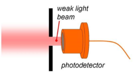
OSA Specifications ExplainedTo understand the technical specifications of an Optical Spectrum Analyser (OSA), it is important to appreciate its basic operation. The simplest approach is to regard the OSA as an instrument that consists of two main components, i.e. a monochromator and a photodetector.
The monochromator is simply an optical bandpass filter, i.e. of all the offered input wavelengths it allows only a narrow portion to pass (Fig 1.a.). The photodetector measures the power (level) of the light that passes through the monochromator.
What is special about the monochromator is that it is able to (repeatedly) sweep the centre-wavelength of the bandpass filter, allowing the photodetector to record a complete optical spectrum.
Essentially, the OSA specifications describe the performance of this measuring method. They describe for example; the accuracy, shape, speed and repeatability of the sweeping bandpass filter, but also the accuracy and linearity of the photodetector circuit.
The specification for the span of the OSA describes the minimum and maximum wavelength range that the OSA can cover with a single spectrum.
The maximum span is the complete wavelength range that the OSA can cover.
Notice that the possibility for “span = 0” is mentioned separately in the specification. In this setting, the OSA uses a fixed wavelength for the bandpass filter (i.e. no wavelength sweep). The display of the OSA now shows the measured optical power (y-axis) versus time (x-axis) rather than wavelength.
Wavelength accuracy
This specifies the maximum wavelength error of the OSA. This specification is important for applications where the absolute wavelength value is measured.
Wavelength linearity
The wavelength linearity of the OSA specifies the amount by which different measured wavelengths can vary from their true values. The specification provides the limits in the deviation from a straight line.
Wavelength linearity is important for applications where the interval between two wavelengths is measured (relative measurement).
Wavelength repeatability
Specifies how accurately the OSA returns to a previously visited wavelength. This is Important for reproducing (repetitive) measurements.

Wavelength resolution settingSpecifies the available resolution settings on the OSA. Each resolution setting should be considered as an indication of the actual resolution used for the measurement.
Each setting corresponds to a specific exit slit size of the monochromator (see image). The actual spectral resolution used in the recording varies with wavelength.
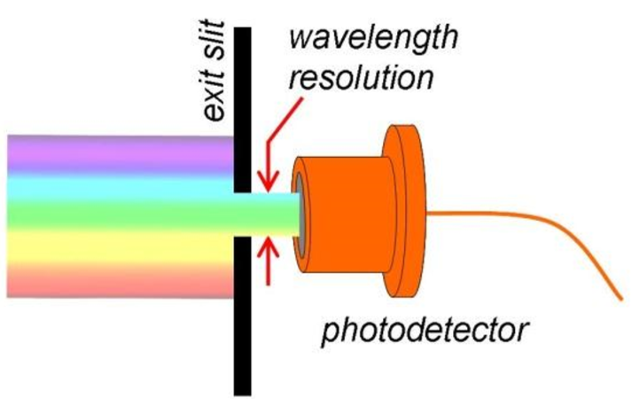
A low resolution (wide exit slit) is important for accurate measurements of the optical power inside a broad spectral peak (e.g. a modulated signal). The complete peak falls through the wide exit slit, meaning that one sample (small measurement error) is sufficient for measurement.
Sweep Speed
The speed at which the OSA completes a wavelength sweep (typically specified for measurement over a 100nm span). The sweep speed is especially important when performing many repetitive measurements (e.g. in manufacturing).
The smallest wavelength step size that can be selected to scan through the spectrum. In “auto setup” (default), the OSA will select a suitable wavelength step size, based on the selected resolution setting.
In manual setup the step can be varied. A small step size means that narrow spectral features are properly recorded. This draws a relation between sampling resolution and spectral resolution.
Specifies the minimum and maximum number of samples that the OSA can use to record a complete spectrum. With a smaller number of samples, the OSA is able to complete the spectral sweep in less time (faster sweep speed). The trade-off is the possibility of missing fine spectral detail.
By default, the OSA automatically calculates the number of samples used for the recording, based on the span and the wavelength resolution setting of the OSA. The OSA will record 5 samples per resolution value of the OSA, so each sample has spectral overlap with multiple neighbouring samples.

For example; There will be 501 samples for a trace with a span of 100nm and a resolution of 1nm. Manually the user can deviate from this by e.g. moving to a larger step size. This will reduce the number of samples and hence increase the measurement speed.
Level sensitivity setting
This specification describes the different circuits that are available to amplify the photodetector signal. Each amplifier circuit has its own signal gain and response time.
A high sensitivity corresponds to a highgain circuit with a relatively slow time response (long integration time), resulting in a relatively slow sweep speed. This setting is important for applications involving a very weak input signal. On the other hand, a low sensitivity setting offers a fast sweep speed with a trade-off on the signal gain. 
Expresses the technique that can be used to reduce the stray light contribution from the measurement. The parts and housing of the monochromator are coated black to keep the amount of stray light to a minimum. To reduce the influence of the remaining amount of stray light, first only the amount of stray light is measured, after which it is subtracted from the actual measurement.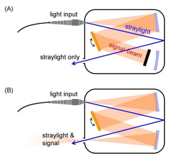
Switch Mode
When "Switch mode" is selected, the OSA will record a complete trace of stray light (A), followed by a complete "normal" measurement trace (B). The stray light trace is subtracted from the measurement trace, and the result is displayed on screen as the end result.
Level sensitivity
Level sensitivity expresses the minimum amount of light that can be detected by the internal photodetector. A lower light level will be lost in the detector noise.Maximum input power
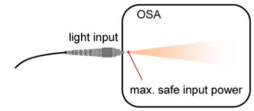
The maximum amount of light (power) that can be handled by the internal photodetector. For narrow spectrum light like lasers, this is the all laser power within a resolution (the complete laser line falls through the monochromator exit slit). You can read it as “+20dBm per laser mode” or “+20dBm per laser line”Maximum safe input power
This is total maximum power that can be injected into the OSA. This can also be very broadband light.
Besides the photodetector, the depolarizer is also sensitive to high optical power. This optical component is located immediately after the entrance to the monochromator.Level accuracy
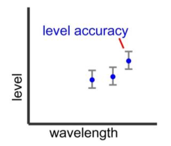
Expresses the accuracy of the OSA for measuring optical power (level). This specification is important for applications that require measurement of the absolute amount of the optical power.Level linearity
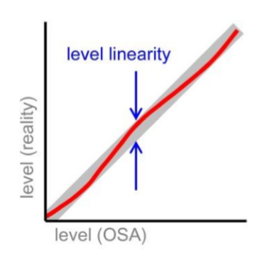
The level linearity of the OSA specifies the amount by which different measured power values vary from their true values. . The specification provides the limits in the deviation from a straight line This is Important for applications that require comparison of different level values (relative measurement)Level flatness
A perfectly flat power density spectrum should produce a perfectly horizontal (flat) OSA recording. This specification tells how well the OSA approximates this perfectly flat trace. This is important for applications that require the comparison of level values, measured at different wavelengths.Dynamic range
Describes the ability of the OSA to suppress the influence of neighbouring wavelengths on each sample. It is an important specification for applications that require the measurement of a weak optical signal next to a strong signal (e.g. laser line). The signal contribution from a neighbouring wavelength causes a blurring of the recorded spectrum. Therefore, the dynamic range specification is important for applications that require a very high spectral resolution.The OSA monochromator acts as a (narrow) bandpass filter (see image). It is the width and shape of the filter that is defined by the dynamic range specification (sometimes referred to as the “optical rejection ratio”)
The filter shape is closely related to the resolution setting of the OSA, and the diameter of the input fibre. For the highest suppression of neighbouring wavelengths (narrowest filter) the highest resolution should be selected, and a narrow core (single mode) input fibre should be used.
Stray light is light that contributes to the detector signal, that is of a different wavelength than the selected wavelength. I.e. it is light that ideally should not reach the photodetector. Stray light potentially can obscure very weak optical signals in the vicinity of a strong spectral peak (e.g. laser line).
Optical Return Loss (ORL)
Specifies the portion of the OSA input light that is reflected back towards the signal source (expressed in dB). Back-reflection can cause instability of the laser source, and therefore introduce an error in the measurement.
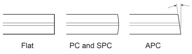
Note: The optical return loss can be significantly improved by moving from the PC-type to an (angled) APC type fibre connector.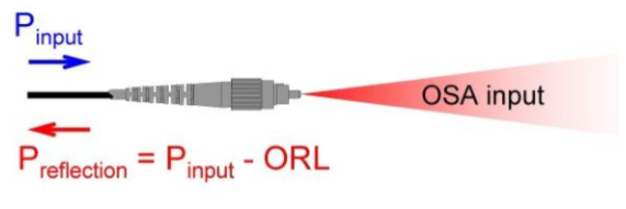
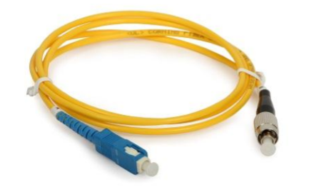
All types of fibre (with diameters up to 800 microns) can be physically connected.
The amount of light that passes through the monochromator (optical throughput) depends on the divergence angle of the input fibre (its Numerical Aperture). As the amount of light that reaches the photodetector determines the measured optical power, the type of input fibre has an effect on the optical power measured by the OSA.
The level measurement of the OSA is calibrated for a single mode (9.5/125) input fibre. When a different input fibre is used the level measurement of the OSA will have a slight offset, which is described in the user manual, and this compensation can be applied in the in the OSA level offset settings.Optical connector
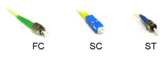
The OSA is supplied with two (replaceable) connector adapters, one for the light input and one for the calibration light source. Three different connector adapters are available; for FC, SC or ST type fibre connectors.The OSA connector adapters are exchangeable, and can therefore be changed as necessary. Note that the light input of the OSA accepts both PC and APC (angled) fibre connectors.